Comparisons and conversion algorithms of vector grating structures
Comparison of raster structure and vector structure
The raster structure and the vector structure seem to be two distinct spatial data structures. The raster structure has obvious attributes and implicit locations, while the vector structure has obvious locations and implicit attributes. Generally speaking, the raster data operation is relatively easy to implement, especially as the representation of patch maps, which is more acceptable to people. While the vector data operation is more complex and many analysis operations are carried out. It is very difficult to implement the vector structure (such as covering operation of two maps, searching neighborhood of points or linear objects). The vector structure is more intuitive to express linear objects, while the surface objects are expressed by describing the boundary. No matter what kind of structure, the data accuracy and data quantity are contradictory. To improve the accuracy, the grid structure needs more grid units, while the vector structure needs to record more line nodes. Generally speaking, the raster structure is only an approximation of the vector structure to some extent. If the accuracy of the graph described by the raster structure is the same as that of the vector structure, even if it is only close to the magnitude, the data will be much larger than that of the latter。
Grid structure is more effective and easier to implement than vector structure in some operations. For example, searching according to space coordinate position is very convenient for grid structure, but searching time for vector structure is much longer. In a given region, statistical index operations, including calculating polygon shape, area, line density and point density, can quickly calculate the results of grid structure, and the results can be obtained by using grid structure. On the other hand, vector structure is more efficient for searching topological relationships, such as computing polygon shape to search neighborhoods, hierarchical information, etc. Only vector structure can fully describe network information. The advantage of vector structure in computing accuracy and data quantity is also one of the reasons why vector structure is more popular than raster structure. For Figure 7-10, assuming that the coordinate accuracy is one-thousandth of ten thousand, that is, five-digit digits, 40 nodes need to be recorded with vector structure. Two double-byte integers are used to record X and Y coordinates for each node, together with the description of other’s explanatory information, 200 bytes are sufficient. It needs 10000*10000=108 bytes if it needs the basic raster records. And it needs about 5 million bytes to record a single byte of raster code (no more than 255). Of course, the actual vector structure of graphics is generally much denser than that of Figure 7-10, but the amount of data is still much less than that of raster structure。
In addition to making a large number of spatial analysis models be easy to implement, the grid structure also has the following two characteristics: (1) It is easy to combine with remote sensing. Remote sensing image is a raster structure based on pixels, which can directly incorporate the original data or processed image data into the raster structure of the geographic information system. (2) Easy to share information. At present, there is no recognized vector structure map data recording format, while the uncompressed grid format, i.e. integer database array, is easy for most programers and users to understand and use. Therefore, data exchange based on raster data for information sharing is more practical。
Many practices have proved that raster structure and vector structure can be equally effective in representing spatial data. For a GIS software, the ideal solution is to adopt two kinds of data structures, such as the coexistence of raster structure and vector structure. It is very important to improve spatial resolution, data compression rate and flexibility of system analysis, input and output. The comparison of the two formats is shown in Table 7-2。
Table 7-2: Comparison of vector and raster formats
Vector data
Advantage
Compact data structure and low redundancy
Favorable for network and retrieval analysis
Good graphic display quality and high accuracy
Shortcoming
Complex data structure
Difficult polygon superposition analysis
Raster data
Advantage
Simple data structure
Facilitate spatial analysis and surface simulation
Strong current situation
Shortcoming
Large amount of data
More complex projection conversion
Mutual Conversion Algorithms
The conversion between vector structure and grid structure is one of the basic functions of Geographic Information System (GIS). At present, many efficient conversion algorithms have been developed. However, the conversion from raster data to vector data, especially the automatic recognition of scanned images, is still the focus of current research。
For point entities, each entity is represented by only one coordinate pair. The conversion between vector structure and grid structure is basically a coordinate accuracy conversion problem, and there is no big technical problem. The vector structure of a line entity is represented by a series of coordinate pairs. When changing into a grid structure, besides changing the coordinate pairs in the sequence into grid row coordinates, a series of grid points need to be inserted between the coordinate points according to the grid accuracy requirement, which is also easy to be obtained by the two-point linear equation. Line entity is changed from grid structure to vector structure, and polygon boundary is expressed as vector structure. Therefore, the conversion between vector structure and grid structure of polygon (surface entity) is discussed。
Conversion from vector format to grid format
Conversion from vector format to raster format, also known as polygon filling, is to assign polygon encoding to all raster points within the boundary of the polygon represented by vectors, thus forming a raster data array similar to Figure 7-4. Several main algorithms are described as follows:
1) Internal Point Spread Algorithms
The algorithm starts with an interior point (seed point) of each polygon and diffuses to its eight-direction neighboring points to determine whether each new join point is on the polygon boundary or not. If it is on the boundary, the new join point is not regarded as seed point. Otherwise, the neighboring point of the non-boundary point is regarded as a new seed point to perform a new diffusion operation with the original seed point, and assigns the seed point to the number. Repeat the process until all seed points fill the polygon and stop at the boundary. The program design of diffusion algorithm is complex, and in a certain grid accuracy, the polygon will be disconnected if two boundaries of the same polygon of complex graphics fall in the same or adjacent two grids, such a seed point can not complete the filling of the whole polygon。
2) Complex Integral Algorithms
The polygon coding method for judging the attribution of the grid arrays one by one is to calculate the complex integral from the closed boundary of each polygon by the judged points. For a polygon, if the integral value is 2πr, the point to be judged belongs to the polygon. Otherwise, it is outside the polygon and does not belong to the polygon。
3) Ray algorithm and scanning algorithm
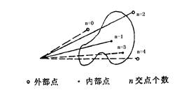
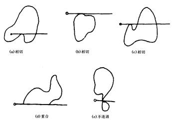
The ray algorithm can judge by point the data grid point whether is outside a polygon or within a polygon. Cite a ray from the inside point to outside point of a graph, and judge the total number of times that whether the ray intersects with all boundaries of a polygon. If the number of times that the ray intersects is even, the point to be judged is outside the polygon, if it is odd, the point to be judged is inside the polygon (Figure 7-12). When using ray algorithm, it should be noted that there are some special cases that may affect the number of intersections when the ray intersects the polygon boundary, which must be excluded (Fig. 7-13)。
The scanning algorithm is an improvement of the ray algorithm. It changes the ray to scan the line along the grid array column or row direction. The judgment is similar to that of the ray algorithm. Scanning algorithm eliminates a lot of calculation of intersection point between ray and polygon boundary, and greatly improves the efficiency。
4)BAF(Boundary Algebra Filling) Filling Algorithm[ Ren Fu Hu ]
The BAF Filling Algorithm is a vector format to raster format conversion algorithm based on integral idea. It is suitable for converting polygon vector data recording topological relations into raster structure. Figure 7-15 shows the conversion of a single polygon. The polygon number is ‘a’, which imitates the process of calculating the area of the polygon area by integral. The initial grid array has zero grid values. The grid rows are taken as the reference coordinate axis. The boundary line is searched clockwise from a point on the polygon boundary. When the boundary is upward (Figure 7-15-a), all the same coordinates are located on the left side of the boundary. The grid is subtracted ‘a’. When the boundary goes down (Figure 7-15-b), all grid points on the left side of the boundary (the forward direction is seen as the right side) are added a value ‘a’, and the polygon transformation is completed when the boundary search is completed。
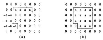
Conversion of a single polygon
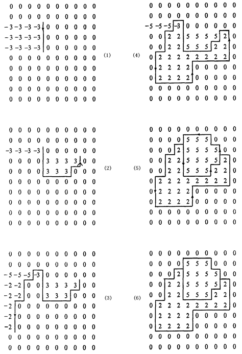
In fact, each digital map is composed of multiple polygonal regions. If the region that does not belong to any polygon (including the region with infinite points) is regarded as a special polygon region numbered zero, then each boundary arc on the map is adjacent to two polygons with different numbers. According to the forward direction of the arc, they are called left and right polygons respectively. It can be proved that for the problem of vector-to-grid conversion of polygons requires only the following operations for all polygonal boundary arcs, regardless of the order of arrangement. When the boundary arc is up, the grid between the arc and the left frame increases by one value (left polygon number minus right polygon number). When the boundary arc is down, the grid between the arc and the left frame increases by one value (right polygon number minus left polygon number). The transformation process of the two polygons is shown in Figure 7-16。
The difference between the boundary algebraic method and other algorithms is that it does not complete the transformation of the relationship between boundary and point by point, but dynamically assigns boundary location information to each grid point by simple addition and subtraction algebraic operation according to the topological information of the boundary, it realize the high-speed conversion from vector format to grid format without considering the relationship between boundary and search trajectory. The algorithm is simple and reliable. Each arc of the boundary is searched only once, avoiding repeated calculation。
But this does not mean that the boundary algebra method can completely replace other algorithms. In some cases, seed filling algorithm and ray algorithm are still used. The former is applied to extract specific regions from raster images, while the latter is used to judge the relationship between points and polygons。
Conversion from raster format to vector format
Conversion from polygonal grid format to vector format is the process of extracting the topological relationship between boundary and boundary of polygonal region expressed by the same number of grid sets, and representing the boundary line of vector format composed of multiple small straight lines。
1)Steps
Conversion from raster format to vector format usually involves the following four basic steps:
(1.1) Polygon boundary extraction: binarization of raster images or identification of boundary points with special values by high-pass filtering;
(1.2) Boundary tracing: searching for each boundary arc from one node to another, usually searching for the next boundary point along seven directions except the direction of entry, until it is connected into a boundary arc;
(1.3) Topological relation generation: for the boundary arc data represented by vectors, the spatial relationship between the edge arc data and the polygons on the original graph is judged to form a complete topological structure and establish the relationship with attribute data;
(1.4) Removal of redundant points and curve smoothness: since the search is carried out on a grid-by-grid basis, the records of redundant points must be removed to reduce data redundancy. Search results, because of the limitation of the accuracy of the grid, may not be smooth enough, the curve needs to be smoothed by certain interpolation algorithms, commonly used algorithms are: linear iteration method; piecewise cubic polynomial interpolation method; axis parabola average weighting method; oblique parabola average weighting method; spline function interpolation method。
2)BDF(Double Boundary Direct Finding)of conversion from polygon raster to vector
The basic idea of the algorithm is to extract the boundary and store the left and right polygon information on the boundary points. Each boundary arc consists of two parallel boundary chains, which record the left and right polygon numbers of the boundary arc. Boundary line search uses 2 * 2. The pattern of four raster data in each window can uniquely determine the search direction of the next window and the topological relationship of the arc, which greatly speeds up the search speed and makes it easy to establish the topological relationship. The specific steps are as follows:
(2.1) Extraction of boundary points and nodes: The 2* 2 raster array scans the whole raster image in row and column directions as a window sequence. If the four rasters in the window have and only have two different numbers, the four rasters are represented as boundary points. If the four rasters in the window have more than three different numbers, they are marked as nodes (i.e., intersection points of different boundary arcs), and the original polygon number information of each raster is maintained. For the case of two or two identical grids on the diagonal line, the disconnection of the polygon is also treated as a node. Figures 7-17 and 7-18 show various cases of nodes and boundary points。
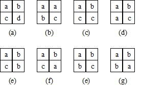
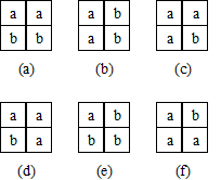
(2.2) Boundary line search and information record of left and right polygons: Boundary line search is carried out by arc segments one by one. For each arc segment, a set of four identified nodes is used. Any set of four adjacent boundary points and nodes must belong to one of the four identified points of a window. First, two polygonal numbers of the starting boundary point are recorded. As the left and right polygons of the arc, the search direction of the next point group is determined by the search direction entering the current point and the possible direction of the point group. Each boundary point group can only have two directions, one is the direction entering the front point group, and the other is the direction of the following point group to be searched. For example, the group of boundary points shown in Figure 7-18 (c) may have only two directions, that is the lower and the right. If the group of boundary points is searched by the group of points below it, the following group of points must be on the right side. Conversely, if the point is searched after the group of points on the right side (i.e., the left and right polygons of the arc are numbered B and a respectively), the search for the following group of points should be determined as the following. It can be seen that the bilateral boundary structure can uniquely determine the search direction, thus greatly reducing the search time. At the same time, the vector structure with left and right polygon number information can easily establish the connection between the topological structure and the attribute data, and improve the conversion efficiency。
(2.3) Removal of redundant points: Removal of redundant points is based on the idea that if three points on a boundary arc are considered to be in a straight line to some extent (satisfying the linear equation), then the middle point of the three points can be considered redundant and removed. The redundant points are caused by searching the boundary point by point (when the boundary is straight), and the redundant points removal algorithm can remove a lot of redundant points and reduce data redundancy。