Spatial analysis process #
The purpose of spatial analysis is to solve a certain type of geospatial-related problem, usually involving a combination of multiple spatial analysis operations. Good spatial analysis process design will be very helpful for problem solving, the general steps are:
To clarify the purpose of analysis and evaluation criteria;
Prepare analytical data;
Perform spatial analysis operations;
Perform a result analysis;
Explain and evaluate the results (if necessary, return to step 1);
Output of results (maps, tables and documents).
Example 1: Calculation of demolition index in road widening and reconstruction #
In this paper, examples will be given to illustrate how to calculate the demolition index in the process of widening and rebuilding a road by building buffer, topological superposition and feature extraction.
1) Defining the purpose and criteria of the analysis
The purpose of this example is to calculate the building area and property value of buildings that need to be demolished due to road widening, the criteria for road widening and remodeling are:
The road is widened from the original 20m to 60m;
Broaden the road should be as straight as possible;
Some buildings with more than 10 stories in the demolition area are not demolished.
2)Data to be analyzed
This example involves two kinds of information, one is the current road map, the other is the analysis of building distribution map and related information in the area.
3)Perform space operations
Firstly, the road to be widened is selected and the buffer zone of the road is established according to the widening radius.
Then the buffer is topologically overlapped with the building floor data to produce a new map, which includes all or part of the building information in the widened area.
4)Perform statistical analysis
Firstly, all or part of the buildings located in the demolition area should be selected, any building that falls into the demolition area and has more than 10 floors above it will be removed from the selection group and the boundary of the road will be partially adjusted.
Then calculate the demolition index for all buildings that need to be demolished.
5)Print the analysis results in the form of maps and tables
Example 2: Site selection of auxiliary construction projects #
This example illustrates how to use the space operation and feature extraction function to select the best construction location for a construction project.
1) Establish the purpose and criteria of the analysis
The purpose of the analysis is to determine the possible location of some specific plots as a mildly polluted plant. The criteria for site selection include:
The land area for plot construction is not less than 10000
m_2;The land price of the plot does not exceed \(1万元\over(m^2)\) .
There should be no public facilities such as kindergartens and schools around the plot to avoid the influence of factory production.
2) Extract data for site selection from the database
In order to achieve the purpose of site selection, two kinds of data need to be prepared, one is a data layer including information of all parcels in the city; the other category is the distribution map of public facilities (including kindergartens, schools, etc.) in the city.
3) Feature extraction and spatial topology overlay
All parcels satisfying conditions 1, 2 are selected from the plot map and topologically superimposed with the common facility data.
4) Perform neighborhood analysis
The neighborhood analysis and feature extraction are performed on the superimposed results, and the parcels satisfying the requirements are selected.
5)Print out the selected plots and related information in maps and tables
Spatial analysis modeling #
The concept of the Cartographic Model #
Model is an abstraction of human beings, before formal construction of physical objects, people often establish a simplified model to grasp the key points of the problem and eliminate the non-essential things that are not related to the problem, so that the model is simpler and easier to grasp than physical objects. Also in order to solve complex spatial problems, people also tried to build a simplified model to simulate the spatial analysis process. Spatial analysis modeling, because it is based on the operation of layer data, which is also called “Cartographic Modeling”. It is a process of answering questions about spatial phenomena by combining spatial analysis command operations, more formally, some definitions are to simulate a spatial decision-making process through a set of sequential and interactive spatial analysis commands acting on the original data and derived data. The result of map modeling is a “map model”, which is a graphical or symbolic representation of spatial analysis process and its data, the purpose is to help analysts organize and plan the analysis process to be completed, and gradually specify the data needed to complete the analysis process. Map models can also be used to study explanatory documents as a reference and material for analytical research.
Map modeling can be an inverse process of spatial analysis process, that is, starting from the final results of analysis, step by step backward analysis to get the final results, which data is necessary, and determine the data to be input at each step and how these data are derived. The following examples will illustrate the process:
Suppose you need to get a result that shows all areas with a slope greater than 20 degrees. The first question is to generate such an image, which data is necessary: If you want to generate an image with a slope greater than 20 degrees, you need an image that reflects all the slopes, is there such an image in the database? If not, ask further along the reverse line of thought: “What kind of data is needed to generate an image of all slopes?”. An elevation data image can be used to generate a slope image. So, is there any elevation data image? If not, what kind of data is needed to generate the image? This process continues until all the necessary data is found. Then, by using graphics or symbols to represent the data and its operation flow in reverse, a map model is obtained. This example is shown in Figure 10-1: Fig. 148 Computing flow for extracting slope greater than 20 degrees # 
In the figure, the rectangular box contains data, the arrow represents the operation command, and the direction represents the operation order.
Examples of map model #
Map models have many representations,in order to further understand the process of cartographic modeling, three examples of map models in different fields are given below, and three different representations are adopted respectively.
1) Quality evaluation model for herbivore habitat
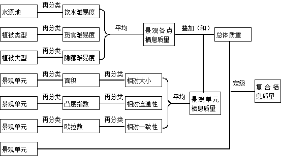
This example is a simplified model for the evaluation of the habitat of herbivores, the model only considers the basic factors that influence the survival of herbivores: water, food, and hidden conditions, as well as metrics for the area, connectivity, and fragmentation of landscape units, the model form is shown in Figure 10-2: Fig. 149 A model for evaluating the habitat quality of herbivores # 
In the figure, the order of operation is from left to right, from top to bottom, the original data and derived intermediate data and result data are in the rectangular box, and the text on the rectangular box connection is the operation command.
2) National Forest Park Location Model
This example is a model for establishing a national forest park for a certain place, which is a model with a known data source and need to extract spatial information. Data sources include road and rail distribution maps (linear features), forest maps (planar features), and town maps (planar features). The map model can be represented in the following form:
Table 10-1: National Forest Park Location Model
Step | Operation command |
|---|---|
Find out all forest areas 1 is woodland, 0 is non-woodland | Re classification |
Boundaries of adjacent polygons with identical attributes in merged forest classification maps | Grouping |
Find areas 0.5 km from roads or railways | Buffer analysis |
Find an area 1 kilometre from a highway or railway | Buffer analysis |
Identify non-urban areas 1 is non-urban and 0 is urban. | Re classification |
Identify areas in forest areas, non-urban areas, and within 0.5 to 1 km of roads or railways | Topological superposition analysis |
Combine polygons of the same attribute | Grouping |
3) Regression prediction model for wood damage
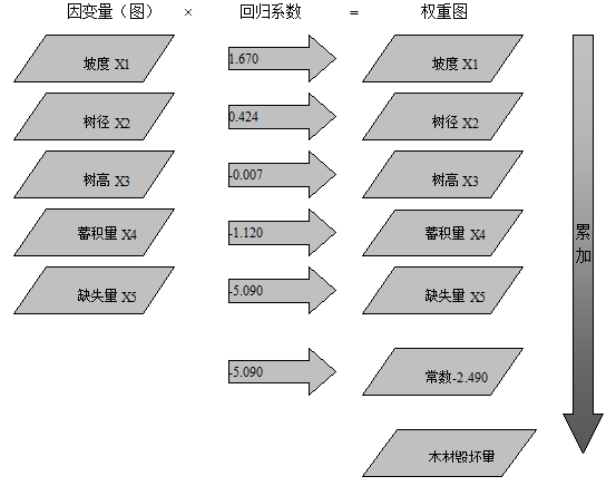
According to the statistical data and empirical equation for many years, this case is a regression prediction model of wood damage when cutting timber in a forest farm.
The dependent variables of the model are slope, tree diameter, tree height, volume, and lack of vector. The formula is as follows:
The map model can be represented in the following form (Fig. 10-3): Fig. 150 Regression prediction model for wood damage # 
Map model implementation #
Most GIS software provides macro command or script description language, which can express all kinds of map models mentioned above as the sequence of GIS operation commands, and complete the whole model process automatically by batch processing. For example, a slope map generated from DEM image can be expressed as a GIS command format:
CALC Slopemap = slope ( DEMmap )
Generating a new graph from multiple original layers can be written in the following form:
Newmap = f (Map1,Map2,…… )
F () denotes a GIS command.
Some GIS software also provides the function of writing complex functions. It can even express a complete map model with multiple functions on a command line as follows:
Newmap1,Newmap2,……=f1,f2,f3,…….( Map1, Map2,……, Newmap1,Newmap2,……)
In the equation, Newmap1, Newmap2, … is a derived intermediate layer.
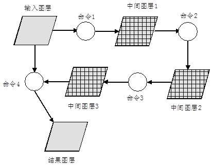
There are also some GIS software that provide advanced visual map modeling aids, users only need to use the tools provided to draw the flow chart of the model in the window, specify the meaning of the flow chart, the parameters used, matrix, etc. The design of the map model without the need to write complex command programs. Visual map modeling tools provide users with a high level of design tools and tools that allow users to focus more on professional research (Figure 10-4). Fig. 151 A GIS model represented by a flow chart # 